Promag 10/50/53electromagnetic flowmeter
1. installation position
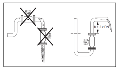
Installation position:
measuring tube,will increase
.measurement error.
therefore,Please avoidthe following installation locations:
The highest point of the pipeline, easy to accumulate bubbles!
● Installed above the downward emptying pipe.
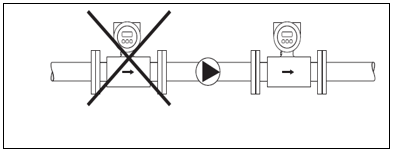
pump:
do not install the sensor on the inlet side of the pump. to avoid pumpingloss
bad measuring tube lining. When using piston pumps, diaphragm pumps or peristaltic pumps
need to install pulsating flow buffer.
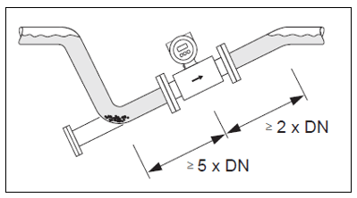
Non-full pipe:
pipes with inclined non-full pipe state shall be equipped with bleed ports.
ATC detection(EPD)function detects pipeline status:Full or non-full pipe
status.
Solid residue accumulation should be avoided!Do not install the sensor on the tilt tube
channel, it is recommended to install a relief valve.
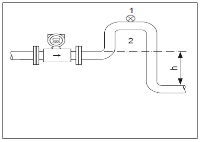
Vertical Duct:
is longer5m(16feet),needs to be in the sensor's
. to avoid damage to the measurement during pumping
pipe lining. This measure also prevents the system from being produced by a pressure drop.
anger cave.
Installation on vertical pipe(h> 5 m/16ft)
1.relief valve
2.siphon
2. Anndirection:
the best installation orientation helps to avoid gas accumulation and residue in the measuring tube
slag accumulation. In addition,in order to correctly measure certain special fluids,can
Choose the following accessories:
● Electrode cleaning circuit(ECC):for preventing conductivity in measuring tubes
media accumulation,such as when measuring the easy adhesion of the fluid
● ATC inspection(EPD)Function:indetection nonFull Pipe,as measured
amount of degassing fluid or changing process pressure
● Replaceable measuring electrode:when used to measure abrasive fluids(only
Promag W)
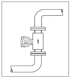
hangingStraight installation:
self-emptying pipeline system and empty pipe detection function(EPD)or electric
Open circuit detection function(OED)measuring systems
bit.
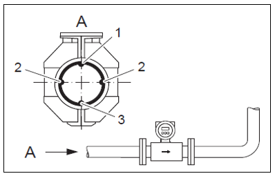
waterPingInstallation:
the measurement electrode plane must be kept level, which can prevent air.
to the bubble.
The empty pipe detection function is only used when the measuring pipe is installed horizontally and the transmitter housingvertical
straight up to work properly. Otherwise, when the pipe is half full or empty
tube status,cannot guarantee that the ATC detection function will work properly.
1. EPDelectrode(ATC detection) : (does not applyPromag H
DN2-15,1/12 '-/").
2.measuring electrode(signal detection)
3.reference electrode(potential balance) :does not applyPromag H
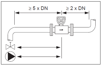
Front and rear straight pipe sections:
if possible.sensor should avoid such as valve and tee
pipe, elbow and other pipe fittings.
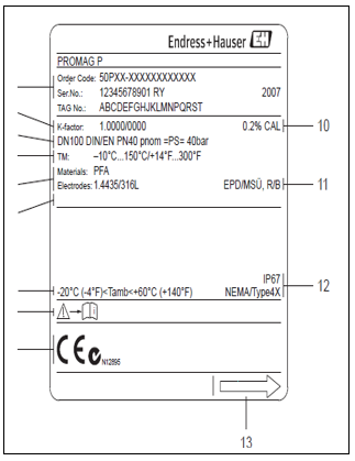
sensor nameplate:
1, order number/Serial Number
2, calibrationKcoefficient/Zero
3, caliber/pressure rating
4, fluid temperature rangeTM:measuring tube
5, Materials:lining/electrode
6and special products
7. Allowable ambient temperature
8. Comply with equipment documents
9, device version(certification, certificate)
10, calibration tolerance
11. Additional Information() :
EPD/MSU:empty pipe detection electrode
R/ B:reference electrode
12, protection grade
13, fluid direction
3. vibration:
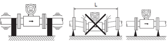
if the vibration is very strong,attention is paid to fixing the pipeline and sensor. prevent
Equipment Vibration(L > 10 m/33ft)
Attention:if the vibration is very strong,It is recommended to install the sensor separatelyand
transmitter.
4. base and support
If the nominal diameter isDN≥350 (≥14 ") ,Please install the sensor
is mounted on a base with sufficient load-bearing capacity.
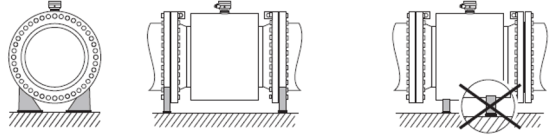
Attention:damage!Do not use the outer frame to bear the weight of the sensor.
amount. The deformation of the outer frame may damage the excitation wire inside the sensor.
circle.
five potential balance onegrounding
The measured fluid and sensor equipotential are accurately measured by electromagnetic flowmeters.
. Most sensors are equipped with a standard reference electrode,
to ensure equipotential connection. Usually,no other action is required or
use groundingring ensurespotential balance.
Promag L,Promag WandPromag Preference electrode(standard
quasi).
●Promag H
a no reference electrode. Connection to the measured fluid through a metal process
equipotential.
-Systems with plastic process connections,must be implemented using a grounding ring
system potential balance.
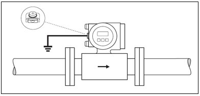
Standard conditions
When using the equipment in a grounded metal pipe,through the transmitter
the ground terminal.
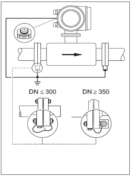
special circumstances
flow meters are installed in:
● In ungrounded metal pipes
This connection method also applies:
● When the system potential balance cannot be achieved by regular method
● When extremely high balancing currents may occur
Both flanges pass through the grounding cable(copper wire,cross-sectional area of at least6
mm2 ( 0.0093 in2)Connected with pipe flange,and ground.
Connect the transmitter or sensor terminal box to the dedicated ground terminal,
realize the system potential balance.
●DN≤300 (12 ') :direct grounding cable through flange bolt
installed in
on the conductive coating of the flange.
●DN≥350 (14 ") :grounding cable directly installed in the metal bracket
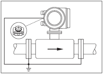
flow meters are installed in:
● In plastic pipes
● In pipes with insulating lining
This connection method also applies:
● When the system potential balance cannot be achieved by regular method
● When extremely high balancing currents may occur
via additional groundingring implementationsystem potential balance. Groundingring throughconnected
ground cable(copper wire,cross-sectional area of at least6 mm2 ( 0.0093
in2))to the ground terminal. When installing the grounding ring,Please observe Ann
the requirements of the installation guide.
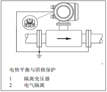
flow meters are installed in:In pipeline with cathodic protection unit
meteor meter shall be installedin pipes of equal potential. Only through grounding electricity
cable(copper wire,cross-sectional area of at least6 mm2 ( 0.0093 in2)will
two pipe flanges are connected. Straighten the ground cable through the flange bolt.
is mounted on the conductive coating of the flange.
This connection method also applies:
.must comply with the requirements of the applicable codes for equipotential installations.
.piping and the flow meter.
.mounting material must meet the application torque requirements.
VI.the length of the connecting cable
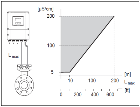
When installing the split instrument,Please follow the following points:
● Fix the cable in the metal shield pipe. The movement of the cable will
,especially when the conductivity of the fluid is low.
● Do not lay cables near electrical equipment and switch cabinets.
●Please make suretransmitter and sensor equipotential.
● Allowable cable lengthLmaxdepends on the conductivity of the fluid.
gray shaded area=allowable range
Lmax=connection cable length(unit is[m/] /[ft])fluid conductance
rate(unit is μS/cm)
7.Promag LSensor Installation
● Mounted on two sensor flanges(DN 50...300)
is usedFixingflange,to suck protection in transitPTFE
lining. Therefore,Before installing the sensor in the pipe,
remove these protective plates.
● During device storage,do not remove the protective panel.
● Ensure that the flange lining is not damaged or removed.
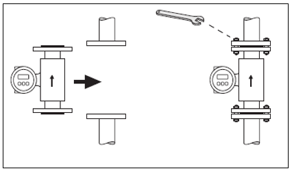
Attention!
Screws, nuts and sealing rings are not included in the scope of supply.,must be made
provided by the customer. The sensor is installed between two pipe flanges:
● Required torque must be observed
● If a grounding ring is used,Please follow the installation instructions included with the delivery.
line operation.
● To comply with the technical specifications of the equipment,requirements are performed in the measurement section
same center installation
Packing
Observe the following instructions when installing the sealing ring:
● Hard rubber lining → Additional sealing ring is always required!
● Polyurethane lining → No sealing ring required.
●PFTEMeasuring tube lining,not required.
●DINflange,use only in accordanceDIN EN 1514-1Requirements
.
● Make sure that the installed sealing ring does not extend into the cross-sectional part of the pipeline.
Attention!Risk of short circuit!Do not use conductive sealing materials,example
such as graphite!measuring tube,makes the measurement signal short
.
screw tightening torque(Promag L)Detailed Form
9.Promag PSensor Installation
Attention!protection plates mounted on the flanges of the two sensors
PTFETherefore, it should be removed before installing the sensor.
● During device storage,do not remove the protective panel.
● Ensure that the flange lining is not damaged or removed.
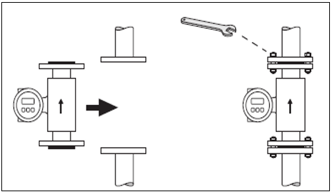
Attention!
Screws, nuts and sealing rings are not included in the scope of supply.,must be made
provided by the customer.
sensor is installed between two pipe flanges:
● Required torque must be observed
● If a grounding ring is used, please follow the installation instructions included with the delivery.
line operation.
Seal Ring-Installation:
Observe the following instructions when installing the sealing ring:
●PFAorPFTEmeasuring tube lining,not required.
●DINflange,use only in accordanceDIN EN 1514-1Requirements
.
● Make sure that the installed sealing ring does not extend into the cross-section of the pipeline.
Attention!Risk of short circuit!Do not use conductive sealing materials,example
such as graphite!measuring tube,makes the measurement signal short
.
screw tightening torque(Promag L)Detailed Form
TenPromag HSensor Installation
packing makeused:when connected during installation,to ensure that the relevant seals
ring clean and dust-free,is centered correctly.
Attention:When using metal process connection,must be firmly tightenedSnail
silk. The process connection forms a metal connection with the sensor, which can be confirmed.
the specified sealing pressure.
● For plastic process connections,Observe maximum torque values for greased threads
(7 Nm/ 5.2lbfft). In the process connection and plastic butt flange
.
● The sealing ring should be replaced periodically according to the application,especially.
(sterile type)!sealing ring
depends on the cleaning cycle, the fluid temperature and the cleaning temperature. Seal ring replacement
replacement parts can be attached
pieces are ordered separately.
Using and installing the grounding ring(DN 2 - 25,1/12 '- 1') :
to plastic process connection(e.g. flange connection or adhesive connection) ,will
the potential between the sensor and the fluid must be secured by an additional grounding ring
balance. If the grounding ring is missing,Electrochemical reactions can damage the electrode,
thereby affecting the accuracy of the sensor or causing damage to the sensor.
grounding ring(including sealing ring)is installed inside the process connection.
end face distance is not affected.
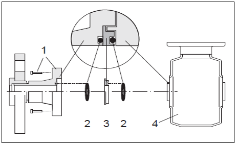
Install the grounding ring
1 =process connection hexagon bolt
2=0ring sealing ring
4 =sensor
3 =grounding ring or plastic ring(placeholder part)
a.loosen four or six hex bolts(1) ,from sensor(4).up and down
removal processconnection.
B.Remove the plastic ring from the process connection(3), including two0Ring Dense
Packing(2).
C.will one of them0ring sealing ring(2)Plug Backprocess connectedconcave
in the slot.
d.metal grounding ring as shown(3)into the process connection.
e.will be the second0ring sealing ring(2)is inserted into the groove of the grounding ring
.
f.Connect Processesloading backin the sensor. During installation,Please
ensure compliance with the maximumTorque value(7 Nm) (5.2Ilbf
ft).
Welding the sensor to the pipe(welded pipe joint)
Attention!
Risk of damage to electronic components!Please make surewelding equipment failed to pass
the sensor or transmitter is grounded.
a.Please spot weld process connection,fix the sensor in the pipe.
suitable welding fixture can be ordered separately as an accessory.
B.Twistpine processthe screw on the connecting flange
(including sealing ring).
C.welded into the pipe.
Ann sensorloading backin the pipeline.
during installation,Please make surethe sealing ring is clean and correctly positioned.
Notemeaning!
● When welding correctly on thin-walled pipes conveying food,even Ann.
is equipped with sealing ring,will not be due to heat
damage. However,recommended to remove the sensor and seal before welding.
● If disassembly work is to be carried out,must be able to open the pipe for approx.8
mm(0.31 in).
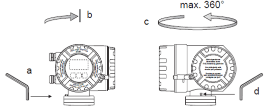
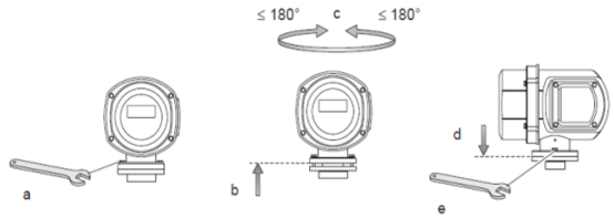
Ten--, rotary transmitter housing
when it is inconvenient for the customer to observe the meter on site,can be rotated
displays the table header.
nonExplosion-proof areaField type aluminum housing:
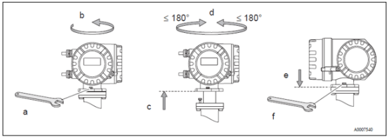
a.Twistloosely fixedScrew
B.clockwise to the stop block(thread top
Department)
C.Turn Transmitter Housing Counterclockwise(the largest360°)to desired position
.
1area orCI. I Div. 1used in explosion-proof occasionsField type aluminum housing
swivel field type stainless steel housing:
XII.Mounted Wall Enclosure
1, directly installed on the wall
determine the ambient temperature does not exceed the allowable range( -20 -- 60°C)Ann
installed away from light,Avoid direct sunlight.
with the cable inlet facing down
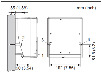
1.Wiringcavity
2.Fastening screwsM6:max.o6.5mm (0.25");
screw head:max.o10.5mm (0.4")
3.mounting holes for fastening screws on housing
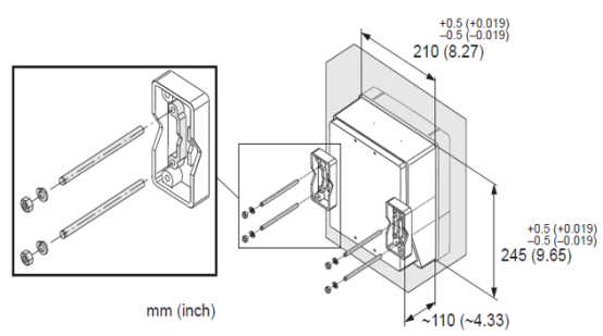
2, column type installation dimension drawing
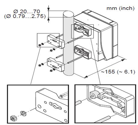
3, disc installation dimension drawing