Pipingis full pipe statusis the premise of accurate measurement of thermal flowmeter
conditions. Therefore,installation flow meter Please note the followingbegged.
1. installation position
●-perturbed fluid state on an instrument based on thermal diffusion principle measurements
is huge.
.comply with the requirements for the length of straight pipe sections before and after the recommend.
●rich engineering practice experience is the correct design and safety of pipeline systems.
the premise of loading.
●Ensure the correct installation direction and installation position of the sensor.
●take necessary measures to reduce or avoid condensation(for example:
Installation of condensate separator, thermal insulation, etc.).
●must comply with the maximum allowable ambient temperature and medium temperature range.
begged.
●Install the transmitter in a cool place, or install a protective cover.
●Based on mechanical structure considerations,to protect the pipeline,installation weight
,Recommended mounting base.
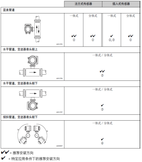
① When measuring saturated gas or impure gas,is recommended for vertical
pipe and flow up,Condensation Reduction/the shadow of pollution
ring.
② Strong vibration or unstable installation,is not recommended.
③ Only applicable to pure/dry gas. If adhesion may occur
or condensation occurs,Do not take horizontal pipe and transmitter table
the installation direction with the head down. Sensor Installation Reference
④ Measurement of humid gas or saturated water gas(for example:biogas),
shall be installed on inclined pipes(a = max. 135*).
2.insulation
measurement of moist gas or saturated water gas(for example:steam),shall
Insulation of piping and flowmeter housing,to prevent water droplets penetration
into the measuring sensor.
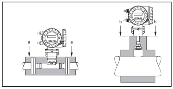
T-mass 65Fand65I
a.flange type sensor
B.plug-in sensors
3. thermal flowmeter
-perturbed fluid state on an instrument based on thermal diffusion principle measurements
is huge. Usually,The thermal flowmeter should be as far away from the disturbance source as possible.
loaded.
details please referISO 14511standards.
●When there are two or more disturbance sources on the upstream side of the flowmeter,should comply
the length of the recommend front straight pipe section with the strongest disturbance source. For example:in pipeline
elbow front installationhas a valve,valveand flowmeter
degree shall be50 x DN.
measurement of extremely light gases(for example:helium and hydrogen),all before
The length of straight pipe section shall be doubled.
Minimum length of straight pipe before and after recommend(without flow regulator) :
Flange sensor
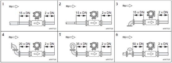
1 =reducing tube; 2 =Expansion pipe; 3=90° elbow orTtype
pipe; 4=2x90° elbow;
5=2x90° elbow(3); 6 =control valve
plug-in sensor
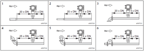
1 =reducing tube;2 =Expansion pipe;3=90° elbow orTtype
pipe; 4=2x90° head; 5=2x90° elbow(3)
; 6 =control valve or pressure regulator
-General thermal mass flow meter installation requirements(reducing tube, expanding pipeand
90° elbow orTtype pipe) :
Front straight pipe length Flange sensor: 15 x DNOPlug-in
sensor: 20x DN
Rear straight pipe length Flange sensor: 2x DNOplug-in sensing
:5xDN
4. orifice plate flow regulator
cannot meet the length requirements of front and rear straight pipe sections,recommended to install orifice flow
quantity adjustment0.
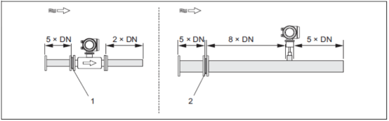
1 =flange type sensors; 2 =plug-in
sensor
plug-in sensor65I
application pipe diameter range isDN 80 .. 300 mm(3...12"). Stream
regulator must be installed in the upstream pipe of the sensor,Front straight pipe
segment length is8 x DN. The flow regulator itself also needs5 x DN
.
Flange sensor65F
EndressHauserspecial designt-mass Fsensor(mouth
diameter isDN 25 ..100(1' ... 4")).offers multiple mounting hole types
and installation dimensions,an orifice plate can meet a variety of different flanges at the same time
Excitationlevel(for example: CI. 150andCI. 300).
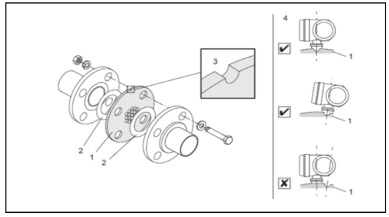
Flow Regulator-Installation:
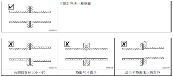
flow regulator and gasket required with two pipe flanges and flow meter method
blue match. Only installations that match the flange bolt holes are allowed
Nut,ensure correct positioning. Positioning grooveneeds to be in the same position as the transmitter.
-level. Influence of Flow Regulator Installation Error on Measurement Accuracy
is small.
1 =orifice plate flow regulator;2 =sealing ring/Washer;3 =fixed
slot; 4 =the calibration slot in the same plane as the transmitter
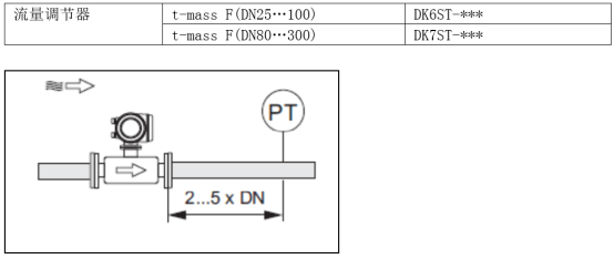
Length of rear straight pipe section with pressure measurement
Excitationmeasuring point shall be installed on the pipeline downstream of the measuring instrument,to be sure.
The process connection of the pressure transmitter has no effect on the flow entering the measurement point.
ring.
Attention!
●To optimize measurement performance,recommend ordering at the same timet-mass Fsensing
and Flow Regulator,enables both to be calibrated at the same time. That's right.
has little effect on measurement performance.
●nonEndressHauserflow regulatorst-
mass Fsensor is matched for measurement,the fluid state and pressure in the pipeline
drop possiblecan affect measurement performance.
●bolts, nuts, sealing rings, etc. are non-standard supply parts,need to use
households bring their own.
5. piping systems
●The connecting pipe shall be consistent with the inner diameter of the flowmeter. The deviation of the maximum pipe diameter shall not be
can exceed:
-Caliber< DN 200 (8'):1mm (0.04 inch)
-Caliber ≥DN 200 (8):3mm (0.12 inch)
is reinstalled,shall be free of metal particles and abrasive particles,-
stopstartup
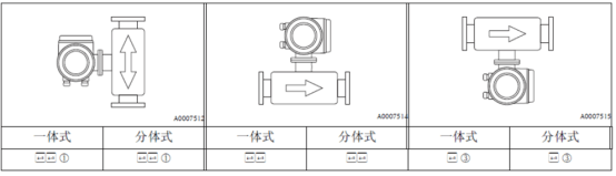
VI,Installation direction of thermal mass flow meter:
Always make sure that the arrow on the sensor points to the direction of the gas in the pipe
.
flange type
plug-in
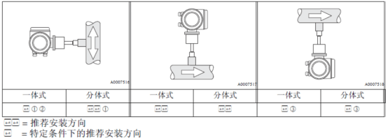
① When measuring saturated gas or impure gas,Vertical pipe recommended
channel and flow upward,reduce the effect of condensation or contamination.
ring.
② Severe vibration environment or unstable installation,Not recommended
this installation direction.
③ Only applicable to clean gas measurement/dry gas. Measurement is very humid
gas or saturated water gas(for example:biogas) ,Do not from the level
the bottom of the pipe. The tilt should be taken as shown in the figure below
Pipe installation direction(moutha =135°)
7. Insertion Sensor Installation
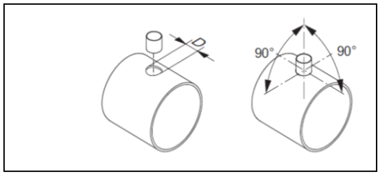
welding seat:
be careful.!
is installed in a thin-walled rectangular pipe,Please use the appropriate sensor
Rack Installation.
D = 031.0mmsoil0.5mm (0 1.22'soil0.019 ")
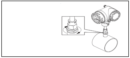
adjusting the position of the plug-in sensor:
Inserting the sensor into the welding socket,Hand tightening under the fastening sleeve
nut, then use wrench(42 mm)Tightening14/4circle.
be careful.!
●NPTthread:Use thread sealing tape or sealant
●G1Athread:The sealing ring must be fitted(Standard supply parts)
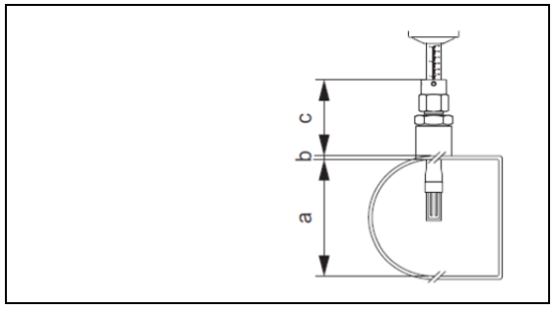
Insertion Depth:
a.circular pipe inner diameter.sensor is installed vertically,rectangular pipe
Pipe height;sensor is installed horizontally,pipe width of rectangular pipe
degrees.
(a =min. 80mmor3 ')
calculate insertion depth: (0.3 x a)B c2mm
(Insertion Depth=(0.3.A) B (C1 C2) 0.079
inch)
B.Pipe wall thickness
c.pipes,includes the sensor pipe connector and
line replacement mounting kit optional).
plug-in sensors can be
EndressHauserApplicatorselection software(version number
10.02or later versions)or by the following steps. Insert
sensor depends on the required insertion depth. Plug
Depth Calculationvalue must beadjustable in the corresponding plug-in sensorFan
inside.
1.determine the sizeA,B,C1andC2
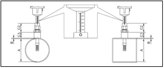
A=circular pipe:Pipe inner diameter(DN)Rectangular Duct/Canal:
parts
B =pipe wallthickness or channel thickness
C1 C2 =the length of the installation assembly and the length of the insertion tube of the fastening sleeve.
through sensor""Quick Settings Menu Calculation Insertion Depth Calculation
insertion depth,requires the following parameters:


2.calculationInsertion Depth Insertion Depth=(0.3-A) B (C1
C2)2mm
3.compares the calculated insertion depth with the parameter values in the following table,got
the correct insertion depth of the plug-in sensor. Insert Depth Calculated Value
must be within the adjustable range of the corresponding plug-in sensor!
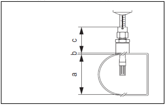
adjust the calculated value of insertion depth:
a.TwistTighten the upper nut of the sleeve,guarantee that the sensor can still be
position adjustment.
B.adjusted according to the insertion depth calculation.
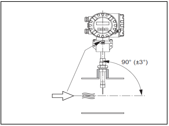
Reference Flow Direction,adjusting the insertion direction of the plug-in sensor
Check and confirm that the sensor installation direction on the pipeline is in line with the flow direction.
90 °
,rotation sensor,Make the arrow on the sensor point in the direction of flow
one.
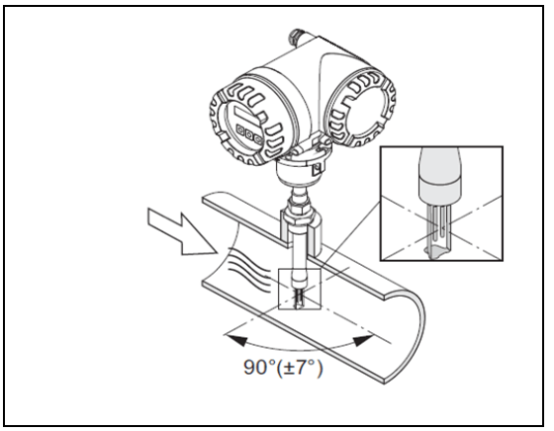
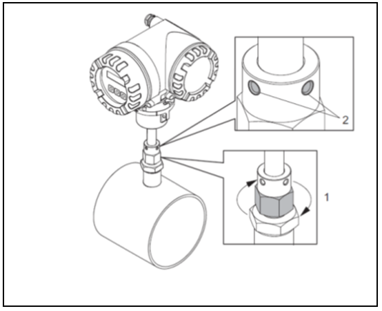
Securing plug-in sensor:
1.Hand tightening fastening sleeve(1) ,fix the sensor. Subsequently,make
liver orifice wrench(36 mm)Clockwise and then tighten1/4circle.
2.Tighten the two set screws(4) , (Allen wrench3mm;
1/8 ").
Warning!Pay attention to the torque size: 4 Nm (2.95lbfft)
3.check to ensure that the sensor and transmitter are no longer rotating.
4.at maximum working pressure,check the measuring point for leaks.
eight,Transmitter Installation Guide
rotationField type aluminum housing:Field type aluminum housing,for non-explosion proof
area
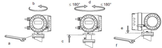
Field Group Enclosure,1area orC.IDm. 1tendon explosion occasion
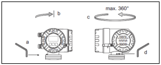
a.loosen the set screw.
B.clockwise,block position
Set(thread top).
C.rotating transmitter housing counterclockwise(max.360°)to desired position
.
d.re-tighten the set screw.
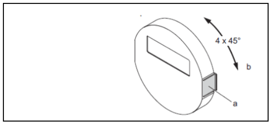
a.,from electronicscavityUpper Panel Removal
.
B.Rotate the display module to the desired position(maximum in both directions
rotation angle is4x45°) ,and reinstall the display module in
electroniccavityon the cover plate.