
one. Installation position
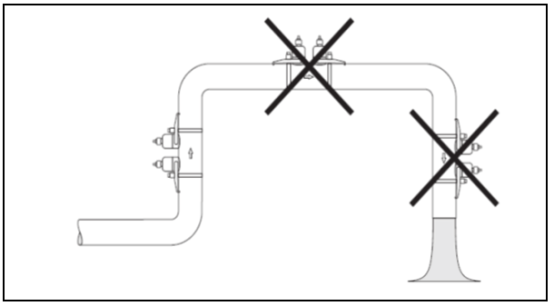
Installation position:The installation position measures that the pipeline is full, and it is a flowmeter.
the premise of correct measurement. Install the sensor in the direction as much as possible..
on the road.
Attention!
measuring tube, it will increase
measurement error.
therefore,Please avoidduct:
●the highest point of the pipeline. Easy to accumulate gas.
●is installed directly above the downward emptying pipe. EasyNon-full pipe
channel status.
II.Installation direction
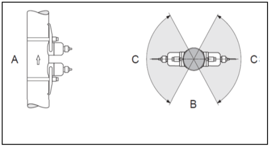
Vertical Duct:the sensor needs to be installed on a vertical pipe,recommendations
selecting a pipe for fluid flow from bottom to top(ViewA). Select this installation
,pipe is stationary,the solid medium included therein will
sinking,gas will rise,away from the sensor. The pipe can be completely self-draining
empty,does not produce solid adhesion.
Horizontal pipe:the sensor needs to be installed on the horizontal pipe,recommendations
in(ViewB)installed in the area shown,to avoid pipes
,to suck the sediment at the bottom of the pipe.
measurement.
Arecommend installation direction,where the fluid flows upward
Brecommend installation range in horizontal piping
CRecommended installation angle, max.120°
three.Front and rear straight pipe sections
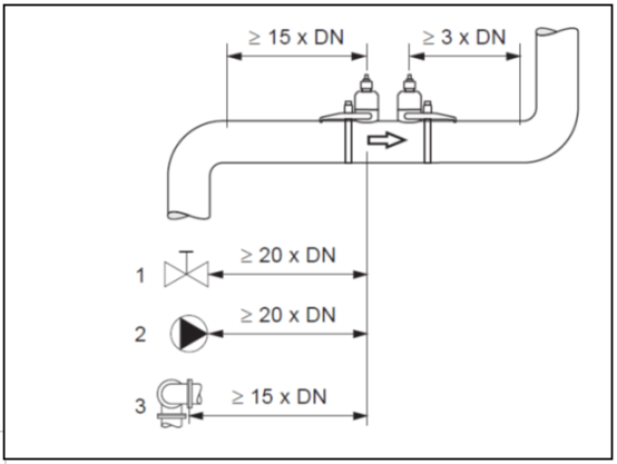
Front and rear straight pipe sections:as possible.,sensor is best avoided
valves, tees, elbows and other pipe fittings. Presence of two or more disturbance sources
,shall respect the length of the straight section before and after the recommend of the strongest disturbance source. Build
Guaranteethe following lengths of front and rear straight pipe sections,to ensure measurement accuracy is met
specifications.
IV.sensor
1, installation stroke
usually,take the following two sensor installation positions:
●Sensor installation position for single stroke measurement:two sensors
on the opposite side of the pipe.
●Sensor installation position for double-stroke measurement:two sensors
, it is installed in the same pipeline.-side.
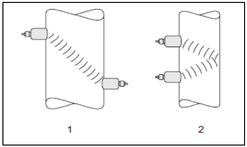
sensor: .
1Sensor installation position for single stroke measurement
2Sensor installation position for double-stroke measurement
2, sensor installation method:
acoustic signal depends on the type of sensor, the pipeline marker, and the number of strokes traveled.
said caliber and pipe wall thickness. The following sensor installers are recommended
:
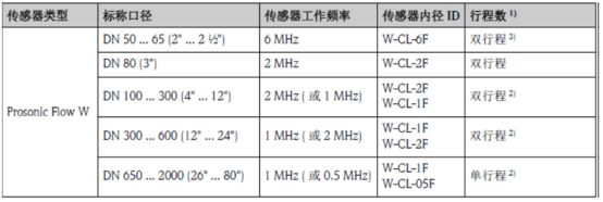
1)The installation position of the bundled sensor is recommended to take a two-stroke measurement. Double
stroke measurement installation position is the simplest and most appropriate installation method,
Even if operation is only allowed on one side of the pipe,can also complete the entire
measuring system. But...,Under certain operating conditions,
sensor to take a single stroke measurement installation position is more appropriate. For example:
●wall thickness> 4 mm (0.16 ')●with lined pipe
Road●acoustic damping
2)for composite materials(for example: GRP)Pipe, partially lined
Pipe, wall thickness> 10mm (0.4)of pipes,or need to enter
heavy acoustic damping fluid flow measurement,Recommended operating frequency
0.5 MHzsensor measurements. At this point,recommend taking a single trip
measuredWsensor installation position.
3)operating frequency is6 MHzsensors for flow rates<10 m
(32.8 Hz/s)media.
●plug-in:Bundled Installation with Binding Strap
trips,or single stroke/The required installation distance of the double stroke depends on:
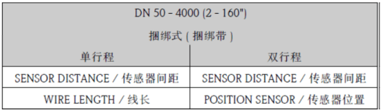
3, installation accessories
Before installation,be determined in advance. Ann
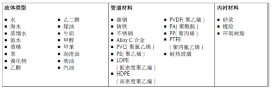
packing spacing is related to fluid type, pipe material and actual pipe diameter.
off. Common fluids and pipe materials listed in the following table have been built into the transmitter.
Material and Pipe Lining Material:
3.1built-in tables
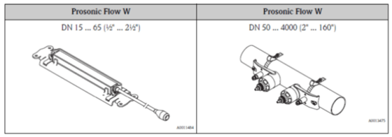
3.2Mounted Bracket
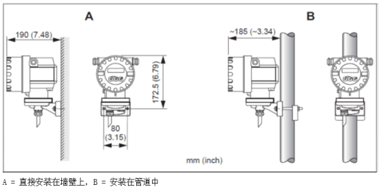
3.3mounted transmitter
can install the transmitter in the following ways:
Wall Mount
● Column installation(bandspecial amine assembly)
be careful.!
Do not exceed the ambient temperature range of the installation point(- 25... 60°C (-
13... 140 f).Avoid direct sunlight.
To install the equipment in warm piping,must ensure that the enclosure temperature
does not exceed the maximum allowable temperature value60°C
five.sensor is fixed as follows:
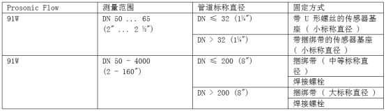
1.Mounting strapUscrew(small nominal diameter)Ann
in nominal diameterDN≤32 (1/4 ")on the pipeline
sensor:ProsonicFlow(DN 15- 65/1/2-21/2')
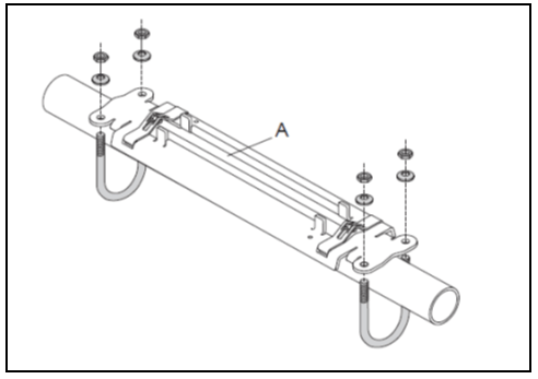
1.disconnect the sensor from the sensor base.
2.position the sensor base on the pipe.
3.willUscrew into sensor base,and slightly lubricate threaded section
points.
4.screw the nut toUShaped Screw Upper
5.adjusting the base to the correct position,and tighten nuts evenly.
6.Visible pipe surface"A"must be sufficiently flat,to ensure good
acoustic contact effect.
2.Installing sensor base with binding strap(small nominal diameter)installed in
Nominal diameterDN > 32 (11/4")on the pipeline
DN 15- 65/1/2-21/2sensors
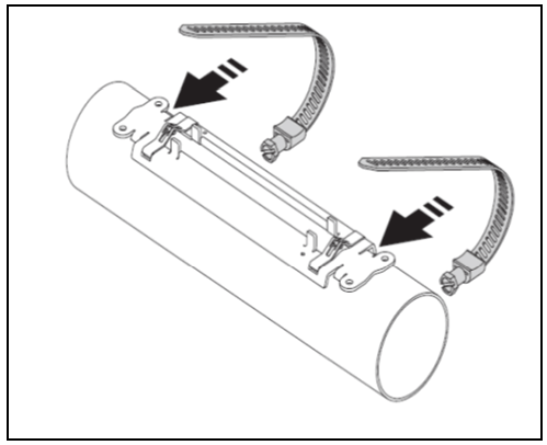
1.disconnect the sensor from the sensor base.
2.position the sensor base on the pipe.
3.Wrap the strap around the sensor base and pipe,be careful not to twist.
twistedbinding straps.
4.Thread the binding strap into the binding strap latch(tensioning screw push up)
5.tighten the binding strap as much as possible by hand.
6.adjust the sensor base to the correct position.
7.pressing down the binding screw,Fastening binding strap,Make Bundledbelt cannot slide
move.
8.if necessary,After cutting the strap,.
9.Visible pipe surface"A"must be sufficiently flat,to ensure good sound
learning contacteffect.
3.Pre-installed Bundling Strap(Medium nominal diameter)installed in nominal diameterDN!
≤200(8 ")on the pipeline.
DN 50 - 4000/ 2 - 160'sensors:
1)Mounting bolt2)Bundling Strap3)tensioning screw
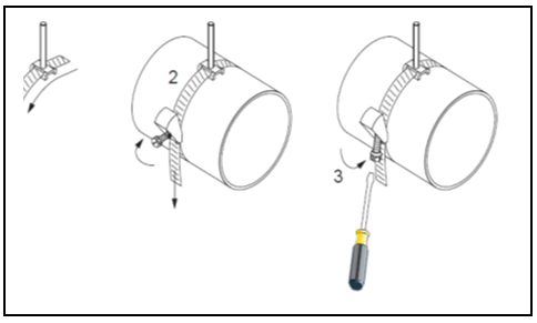
1.install the mounting bolts on the tie-down straps.
2.Wrap the strap around the pipe,Be careful not to twist the binding straps.
3.Pierce the end of the binding strap through the binding strap latch.(tensioning screw push up).
4.tighten the binding strap as much as possible by hand.
5.adjust the binding straps to the desired position.
6.pressing down the tensioning screw,Make Bundledbelt cannot slide
move.
Second Binding Strap
7by first-Bundling Strap Procedure(Steps1 - 7).only slightly
Tighten the second binding strap slightly,for final installation. Bundling belt must
must be OKmove,to make final adjustments.
8.if necessary,After cutting the strap,.
4.Pre-installed Bundling Strap(Large nominal diameter)installed in a nominal diameter range
DN > 600 (24)on the pipeline
DN 50 - 4000/ 2 - 160'sensors
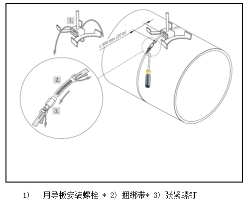
1.measures pipe circumference.
2.cut the strap to length(pipe perimeter32 cm (12.6
in))and trim cutting edges.
3.Install the mounting bolts on the tie-down strap_.
4.Wrap the strap around the pipe,Be careful not to twist the binding straps.
5.Pierce the end of the binding strap through the binding strap latch.(tensioning screw.Push up).
6.tighten the binding strap as much as possible by hand.
7.adjust the binding straps to the desired position.
8.pressing down the tensioning screw,Make Bundledbelt cannot slide
move.
Second Binding Strap
9.the steps for the first strap(Steps3 - 8). Only slightly
Fasten the second binding strap,for final installation. The binding strap must
can move,to make final adjustments.
5.ProsonicFlow WSensor Installation
5.1ProsonicFlow W(DN 15- 65/1/2_21/2
')
Prerequisites
installation distance(Sensor Spacing)
●sensor base installed
material
installation:
●sensor with connector cable
connection cable for connecting the transmitter
Couplant for acoustic connection between sensor and pipe
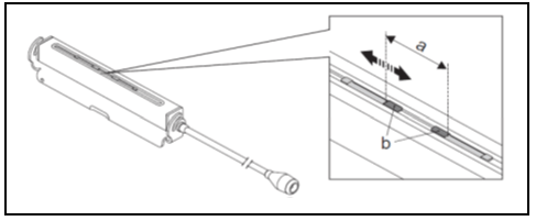
1Adjust the sensor installation space according to the determined sensor spacing value
distance. Push down slightly to move the sensor.
2.Apply an even coat of couplant to the sensor contact surface.
(about0.5-1mm/0.02-0.04in).
3..
Adjust the installation spacing of the sensors according to the sensor spacing valuea)sensor
SpacingB)sensor contact surface
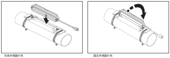
4.secure the sensor housing with an amine mount.
5.connect the connection cable to the connector cable.
5.2ProsonicFlow W(DN 50 - 4000 /2 '-
160 ')
Installation of single stroke measurement(DN 600 - 2000 /24'- 80')
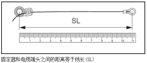
Steps
1.Prepare two measuring wires:
-placement of ends and retainers,ensure that the distance between them is equal to the line length
(SL).
-screw the holder onto the measuring wire.
Note: SL : WIRE LENGTHline length
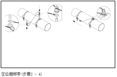
2.Arrange the first measuring steel wire:
-fit the retainer on the mounting bolt that secures the tie-down strap.
-Clockwise "walk in"on the pipeline.
-will measure the wireline will end sleevethe mounting bolts at the movable binding strap.
.
3.Arrange the second measuring steel wire:
-install the end on the mounting bolt that secures the strap.
-will measure the wire counterclockwise"walk in"on the pipeline.
-fit the retainer onto the mounting bolt of the movable tie-down strap.
4.moving strap(including mounting bolts),until two measurementsguide
lines are evenly tensioned,then,Fasten this binding strap,Make the Bundling Strap
cannot slide.
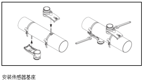
5.Loosening the retainer screw on the measuring wire,from mounting bolt
Remove the measuring wire.
6.Install the sensor base on each mounting bolt,
firmly fastened.
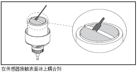
7.on sensor contact surface,from the groove through the center to the opposite side
the edge, apply a layer of couplant evenly.,thickness is approximately1mm
(0.04)..
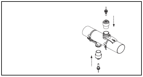
8.insert the sensor into the sensor base.
9.pressing the sensor on the sensor base,rotation:
-
a "click"meshingsensor housing
-Arrow
"close")are aligned with each other.
10.connect the connection cable to each sensor.
installation process. Connect the sensor to
transmitter.
Install the sensor andconnection connectioncable
Installation of Double Stroke Measurement(DN 50- 600 /2'- 24")
Steps
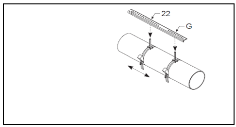
1Use of mounting railsfeetposition the binding strap.
-will install the guide railfeetis marked"POSITION SENSOR/sensing:
position"a specific letter of the drilled hole to fit the bolt in the fixed binding strap.
.
-Adjust the position of the strap.,will be marked"POSITION
SENSOR/Sensor Location"a specific value of the drilling sleeve in the installation guide.
on the rail ruler.
Use of mounting railsfeetdetermine distance(for example,"POSITION
SENSOR G22"/"Sensor LocationG22")
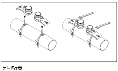
2.tighten the movable binding strap so that it cannot slide.
3.from mounting bolts_.
4.Install the sensor base on each mounting bolt,
securely fastened.
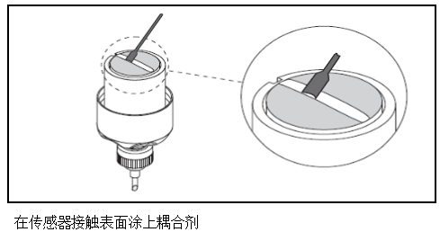
5.on sensor contact surface,from the groove through the center to the opposite side
the edge, apply a layer of couplant evenly.,thickness is approximately1mm
(0.04 ").
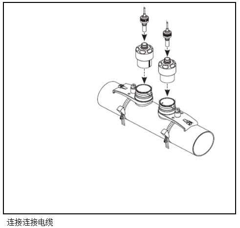
6.insert the sensor into the sensor base.
7.pressing the sensor on the sensor base,rotation:
"clicker"oneAcoustic Engagement Sensor Housing
-Arrow( "close")are aligned with each other.
8.connect the connection cable to each sensor.
installation process. Connect the sensor to
transmitter.