
1. Power/signal wiring
1.1 one current output and two current outputs (optional)
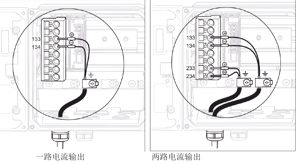
Note: The allowable range of power supply voltage is 12.5 to 30 VDC 133 connection voltage +,134 connection voltage-. The two outputs are 233 + and 234-.
2. Sensor wiring
2.1 standard analog sensor wiring (using CPK9 cable)
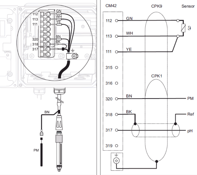
1) The green, white and yellow temperature lines are respectively connected to terminal 112,113,111. 2) The core wire and the black shielded wire of the coaxial line represent the measurement and reference signals respectively, and are connected to the 317 and 318 terminals respectively; the brown equipotential wire is connected to the 320 terminal. 3) The sensor cable shielding layer shall be grounded.
2.2 IsFET analog sensor wiring (using CPK12 cable)
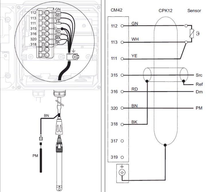
1) The green, white and yellow temperature lines are respectively connected to terminal 112,113,111. 2) The core wire and black shielded wire of the coaxial line represent the measurement and reference signals respectively, and are connected to the 315 and 318 terminals respectively, the red wire is connected to the 316 terminal; the brown equipotential wire is connected to the 320 terminal. 3) The sensor cable shielding layer shall be grounded.
2.3 Memosens Digital Sensor Wiring
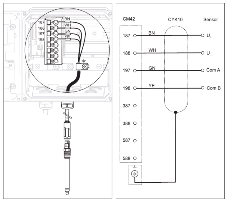
1) Brown, white, green and yellow cables are connected to terminal 187,188,197,198 respectively. 2) The sensor cable shielding layer needs to be grounded. Note: All cable plugs must be tightened and sealed.